article
How Clearance Hole to Clearance Hole Stackup Works — Circular Pattern
When bolts must pass through holes arranged on a bolt circle, small errors in BCD, angle, and hole size all stack up. This guide walks you through the circular clearance hole stackup from scratch — explaining how BCD and angle tolerances convert into a positional shift, how worst-case and RSS results differ, and what to fix when the stackup fails.
Published May 26, 2026
1. The problem this tool solves
Imagine a pipe flange. Two steel flanges bolt together face-to-face, and each has four holes arranged in a neat circle. On the drawing, every hole is at exactly the right angle and exactly the right radius. Assembly should be simple.
In reality, the holes are never quite where the drawing says. The circle is slightly bigger or smaller than specified. The holes are drilled a fraction of a degree off their intended angle. The holes themselves are slightly over or under the nominal diameter. Each of these errors is tiny on its own — but when you try to push a bolt through a misaligned hole in both flanges simultaneously, all those tiny errors add up. That accumulation is called a tolerance stackup.
A tolerance stackup is the process of figuring out how all the manufacturing variations in your parts combine, and whether that combined variation still allows the assembly to work. Here: does every bolt pass through both flanges?
The circular pattern stackup is the same idea as the rectangular (X/Y) version — but the position of each hole is defined differently. Instead of X and Y distances from a corner datum, the hole is located by a radius (the bolt circle diameter, or BCD) and an angle. This article explains what that means, how the calculation works, and how to interpret the result.
2. What makes the circular pattern different
In a rectangular bolt pattern, hole positions are controlled with X and Y dimensions — distances along two perpendicular axes from a reference corner. This is straightforward to measure with a ruler or calliper.
In a circular bolt pattern, holes sit on an imaginary circle. That circle has a diameter — the BCD (Bolt Circle Diameter). Each hole's position is described by two things:
- The BCD — the diameter of the circle all holes sit on.
- The angle — how far around the circle each hole is, measured from a reference direction (usually the first hole or a keyway).
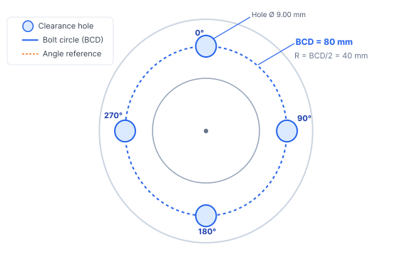 Fig 1 — Top view of a 4-bolt circular pattern. Each hole sits on the BCD circle
at a specified angle. The first hole is the angle reference (0°). All four holes
are 90° apart. Position tolerances in a circular pattern are defined by BCD
tolerance and angle tolerance — not X/Y distances.
Fig 1 — Top view of a 4-bolt circular pattern. Each hole sits on the BCD circle
at a specified angle. The first hole is the angle reference (0°). All four holes
are 90° apart. Position tolerances in a circular pattern are defined by BCD
tolerance and angle tolerance — not X/Y distances.
The key difference from a rectangular pattern: when the BCD or the angle has a tolerance, the hole shifts in a curved path, not along a straight axis. Translating that curved shift into a usable number for the stackup requires a small piece of geometry, which the next sections cover.
3. The inputs: what you need from the drawing
Five types of input affect the circular clearance hole stackup. Once you understand each one, the calculation is just arithmetic (with one square root).
3a. Hole nominal diameter and EBT (Equal Bilateral Tolerance)
Every hole has a nominal size — the intended diameter — and a tolerance that defines how far the actual diameter is allowed to deviate from that nominal. EBT stands for Equal Bilateral Tolerance. It is the one-sided ± value — how far the diameter is permitted to go above or below nominal. An EBT of 0.20 mm on a 9.00 mm hole means the hole can be anywhere from 8.80 mm to 9.20 mm (±0.20 mm on the diameter).
Enter the ± value directly. If your drawing says Ø9.00 ±0.20 mm, enter EBT = 0.20. Do not double it to 0.40. The tool applies a sensitivity of 0.5 to this value internally — this converts the diameter tolerance into its contribution to the radial clearance budget, because the entire stackup is built in radius space (every diameter measurement is halved to work in radius terms).
For the stackup, the worst case for fitting a bolt is when the hole is at its smallest. So the calculation always starts from the minimum hole size.
3b. BCD and BCD tolerance
The BCD is the diameter of the imaginary circle that all the hole centres sit on. On a drawing it might be called out as "4× Ø9.00 HOLES ON Ø80.00 B.C." The BCD itself has a tolerance — the actual circle might be slightly larger or smaller than 80.00 mm.
When the BCD is larger than nominal, every hole moves radially outward from the flange centre — like points on a balloon that's been inflated slightly. When the BCD is smaller, every hole moves inward. This radial shift is the BCD tolerance's contribution to positional error.
Enter the total BCD tolerance range. If the drawing says BCD = 80.00 ±0.15 mm, enter BCD = 80.00 and BCD Tolerance = 0.30 mm (the full range, not the half-value). The tool handles the ±split internally.
3c. Angle and angle tolerance
Each hole's angular position is measured from a reference direction — usually the first hole at 0°, then subsequent holes at equal increments (90° for 4 bolts, 60° for 6 bolts, etc.).
The angle tolerance is how far the actual hole angle is allowed to deviate from nominal. If the drawing says a hole should be at 0° ±0.125°, the actual hole could be at -0.125° to +0.125°. That small angular error shifts the hole tangentially along the bolt circle.
Enter the total angle tolerance range in degrees. ±0.125° becomes 0.25° in the tool. Each hole in your pattern gets its own angle entry — they may be at different angles (0°, 90°, 180°, 270°) but typically have the same angular tolerance.
3d. Coating thickness
If your parts are coated — zinc plated, painted, galvanised, or powder coated — the coating deposits on the inside surface of each hole, reducing the effective diameter the bolt sees. A 0.025 mm coating on each side reduces the hole diameter by 0.050 mm (2 × coating per hole).
3e. Bolt diameter and length
The bolt itself has two relevant dimensions. The nominal diameter is the bolt's stated size (e.g. M8 = 8.00 mm). The maximum diameter is the largest the bolt body is permitted to be under its manufacturing standard (e.g. M8 per ASME B18.2.1 = 8.058 mm). A longer bolt also contributes slightly more camber — a bow in the shank — which pushes against the hole edge.
4. How BCD and angle tolerance combine into a positional shift
This is the key step that is unique to circular patterns. In a rectangular stackup, position tolerance in X and Y is straightforward. In a circular stackup, we need to ask: "If the BCD is at its maximum and the angle is at its worst, how far is the hole centre from where it should be?"
The answer is a diagonal distance — the straight-line gap between the nominal hole centre and the actual worst-case hole centre. To find this, we use coordinate geometry. Here is the idea step by step.
Step 1 — Nominal hole centre position
Place the flange centre at the origin. A hole at angle ? on a bolt circle of radius R (= BCD ÷ 2) sits at coordinates:
Step 2 — Worst-case hole centre position
Now apply both tolerances at once — BCD increases by its tolerance (radius increases by BCD_tol ÷ 2), and the angle shifts by its tolerance ??:
Step 3 — Compute the shift distance
The positional shift is the straight-line distance between the nominal and actual hole centres:
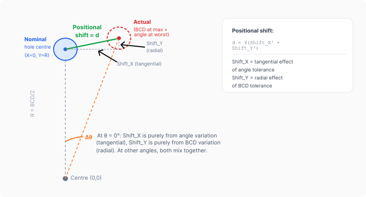 Fig 2 — Geometric breakdown of positional shift. The nominal hole centre (blue, solid) sits at
radius R on the bolt circle. The worst-case actual centre (red, dashed) sits at radius R + ?R
and angle ? + ??. The straight-line distance between them is the positional shift d, which
breaks into a tangential component (angle tolerance) and a radial component (BCD tolerance).
Fig 2 — Geometric breakdown of positional shift. The nominal hole centre (blue, solid) sits at
radius R on the bolt circle. The worst-case actual centre (red, dashed) sits at radius R + ?R
and angle ? + ??. The straight-line distance between them is the positional shift d, which
breaks into a tangential component (angle tolerance) and a radial component (BCD tolerance).
In the stackup, this positional shift plays the same role that the diagonal (v(PosX² + PosY²)) played in the rectangular version — it is the maximum distance the hole centre can be from its intended position.
A 0.175 mm tangential shift and a 0.150 mm radial shift do not produce a 0.325 mm total shift — the hole cannot simultaneously be 0.175 mm off in one direction AND 0.150 mm off in the same direction. The two effects are at right angles to each other, so they combine as a diagonal: v(0.175² + 0.150²) = 0.231 mm. This is always smaller than the simple sum, which is why the geometric approach is more accurate (and less pessimistic) than just adding everything together.
5. The clearance that matters
Once we know the positional shift, the question is: does the bolt still fit? The key number is:
If the effective hole (after coating) is 8.95 mm and the bolt is 8.00 mm nominal, there is 0.95 mm of available clearance. That 0.95 mm must accommodate:
- The reduction from hole size variation (from hole EBT) for each plate
- The hole centre shifting away from true position (from BCD + angle tolerance) for each plate
- The bolt bowing (camber) across its length
If the combined effect of all these fits within the 0.95 mm, the bolt clears. If not, the bolt will bind or fail to pass through both holes simultaneously.
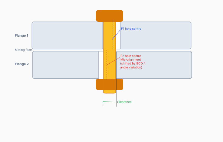 Fig 3 — Side view of a bolt through two flanges. Flange 1's hole centre (blue) is at nominal.
Flange 2's hole centre (red) is shifted due to BCD and angle variation. The bolt must
clear both hole edges simultaneously — the minimum clearance on either side is what the
stackup calculates.
Fig 3 — Side view of a bolt through two flanges. Flange 1's hole centre (blue) is at nominal.
Flange 2's hole centre (red) is shifted due to BCD and angle variation. The bolt must
clear both hole edges simultaneously — the minimum clearance on either side is what the
stackup calculates.
6. The worst-case calculation — step by step
The worst-case method assumes every tolerance is simultaneously at its most unfavourable value. This is the most conservative approach: if the assembly passes worst-case, it will pass under every possible combination of parts.
We will work through this using the example from Section 11 in advance, so the numbers mean something concrete. Two identical flanges, 4 × M8 bolts on BCD 80 mm, zinc plated, holes at 0°/90°/180°/270°. We check the hole at 0° (the results are identical for all four holes in a symmetric pattern).
Step 1 — Find the effective hole diameter
Step 2 — Calculate the EBT contribution for each flange
The hole can be smaller than nominal by up to the full EBT (0.20 mm on the diameter). The formula multiplies EBT by a sensitivity of 0.5 — not because the diameter reduction is only half, but because the entire stackup is computed in radius space. Every diameter-based value (hole size, hole tolerance) is halved to convert it to a radius contribution. This 0.5 sensitivity is consistent across all hole-size terms in the formula:
Step 3 — Calculate the positional shift for each flange
Using the geometry from Section 4, with ? = 0°, R = 40 mm (BCD/2), BCD_tol/2 = 0.15 mm (radius variation), and angle tolerance ?? = 0.25° = 0.004363 radians:
The position contribution term for each flange is:
Step 4 — Calculate bolt camber
Step 5 — Sum all tolerance contributions
Step 6 — Compare with available clearance
A negative minimum gap means there exist combinations of tolerances where the bolt will not pass through both holes. In this example, the stackup fails by a very small margin — just 0.009 mm. The design is borderline and warrants a closer look at the statistical result before deciding to redesign.
7. The RSS method — a more realistic view
The worst-case method assumes every single tolerance hits its worst extreme simultaneously. In practice, this almost never happens. If you manufacture thousands of flanges, the probability that every part is simultaneously at its worst tolerance is extremely low.
The RSS method (Root Sum of Squares) treats each tolerance contribution as an independent random variable and combines them statistically:
The statistical result is clearly positive — +0.486 mm. That means under typical production variation, nearly all assemblies will clear the bolt by a comfortable margin. The tool converts this into a statistical yield percentage using a Z-score calculation.
Use worst-case for safety-critical joints, one-off fabrications, or whenever tolerances are controlled by manual setup. Use RSS as a realistic prediction for volume production on CNC machines with proven process capability. For this example — flanges produced on CNC machining centres — the RSS result (passing) is the more relevant indicator.
8. Understanding your results
| Result field | What it means |
|---|---|
| Min gap (worst-case) | The smallest possible clearance when every tolerance is simultaneously at its worst. If negative, some assemblies will fail. |
| Max gap (worst-case) | The largest possible clearance — the loosest the assembly can be. Rarely a concern for bolt fitment but useful to know. |
| Status: SAFE / UNSAFE | SAFE means even the absolute worst combination of tolerances clears the bolt. UNSAFE means at least one combination does not. |
| Statistical yield % | The probability a randomly assembled joint passes — based on the RSS assumption that tolerances are independent and normally distributed. |
| Contributor chart | Shows each tolerance's percentage share of the total variation (RSS-based). The largest contributor is the best target for improvement. |
In this article's example, worst-case says UNSAFE by 0.009 mm but RSS yields a comfortable +0.486 mm gap with very high statistical yield. For a non-critical flange on a general structure, most engineers would accept this result and proceed. For a pressure-containing joint or a safety-critical connection, worst-case SAFE would be required.
9. The GD&T connection
So far we've described positions using BCD + angle, which is how they appear on many mechanical drawings. Modern drawings often use GD&T (Geometric Dimensioning and Tolerancing) instead, controlling hole positions with a true position callout directly on the bolt circle. Here's how the two relate.
True position on a bolt circle
In GD&T, the position of a bolt-circle hole is controlled with the position tolerance symbol ? in a feature control frame. The tolerance zone is a cylinder of diameter equal to the stated tolerance, centred on the true position of each hole.
A typical callout for a 4-bolt circle might read:
Converting a GD&T position callout to BCD/angle inputs
If your drawing uses GD&T true position (?t) on a bolt circle, and you want to use the circular stackup tool, the simplest approach is to think about what that tolerance zone means geometrically.
A GD&T cylindrical position zone of ?t means the hole centre can shift up to t/2 in any direction from true position. That combined radial shift (t/2) is the same quantity that the tool computes from BCD and angle tolerances. You can therefore estimate equivalent BCD/angle values — or use the position term directly as input to a conservative estimate.
| GD&T callout | What the ? tolerance means | Equivalent input to the tool |
|---|---|---|
| ? ?0.50 | Hole centre within 0.25 mm of true position in any direction | Set BCD_tol and angle_tol to values that together produce a 0.50 mm positional tolerance zone diameter |
| ? ?0.30 | Hole centre within 0.15 mm of true position | As above, targeting a 0.30 mm combined zone diameter |
Suppose , you have template sheet tolerances for angle and BCD and stackup is not passing on those values and now you want to give some manual tolerances to pass the stackup, then best iteration is to keep angular tolerance to zero and put some value in BCD tolerance. This method is equivalent to provide GD&T positional tolerance of diameter equal to the value you providede in BCD tolerance.
10. How to improve a failing stackup
If the tool shows UNSAFE, look at the contributor chart to find the largest term. Reducing the biggest contributor gives the highest improvement per unit of effort.
| What to change | Effect on stackup | Typical impact |
|---|---|---|
| Increase clearance hole diameter | More available clearance — directly reduces the gap | High |
| Tighten angle tolerance | Reduces Shift_X (tangential component) | High |
| Tighten BCD tolerance | Reduces Shift_Y (radial component) | High |
| Reduce bolt length | Reduces bolt camber contribution | Medium |
| Reduce coating thickness | Increases effective hole diameter | Medium |
| Tighten hole EBT | Reduces hole size variation term | Medium |
| Use smaller diameter bolt | More available clearance for same hole | Situational |
In the example above, the positional terms (Pos1 + Pos2) account for about 49% of the RSS variation combined, making them the dominant contributor. The bolt camber contributes about 41%. This means the first action should be either to tighten the BCD or angle tolerance — or to reduce the bolt length if that is easier to change. Tightening the hole EBT would have the least effect in this particular case.
11. A complete worked example
Two steel flanges forming a pipe joint. Bolted together with 4 × M8 bolts on a BCD of 80 mm. Holes at 0°, 90°, 180°, and 270°. Flanges are zinc plated after machining.
| Parameter | Flange 1 | Flange 2 |
|---|---|---|
| Hole nominal Ø | 9.00 mm | 9.00 mm |
| Hole EBT | ±0.20 mm (EBT = 0.20) | ±0.20 mm (EBT = 0.20) |
| Zinc coating | 0.025 mm per side | 0.025 mm per side |
| BCD | 80.00 mm | 80.00 mm |
| BCD tolerance | ±0.15 mm (= 0.30 mm total) | ±0.15 mm (= 0.30 mm total) |
| Angle (1st hole) | 0° | 0° |
| Angle tolerance | ±0.125° (= 0.25° total) | ±0.125° (= 0.25° total) |
| Bolt: M8 hex, nominal Ø = 8.00 mm, max Ø = 8.058 mm, length = 40 mm | ||
Calculation summary
Contributor breakdown (RSS basis)
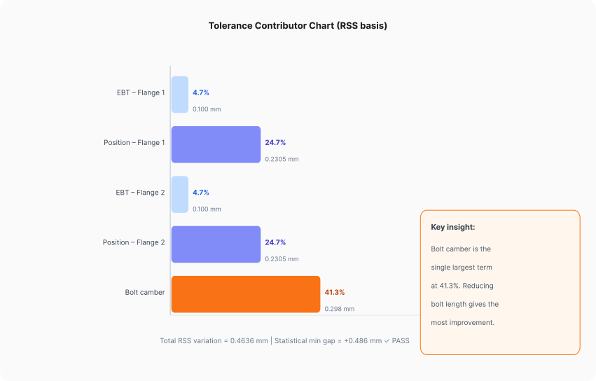 Fig 4 — RSS contributor chart for the worked example. Bolt camber dominates at 41%,
followed by the position terms from each flange (24.7% each). The EBT terms are minor
contributors at 4.7% each. To fix the failing worst-case result, reducing bolt length
or tightening the BCD/angle tolerance gives the most benefit.
Fig 4 — RSS contributor chart for the worked example. Bolt camber dominates at 41%,
followed by the position terms from each flange (24.7% each). The EBT terms are minor
contributors at 4.7% each. To fix the failing worst-case result, reducing bolt length
or tightening the BCD/angle tolerance gives the most benefit.
The worst-case gap is -0.009 mm. Three quick fixes any one of which is sufficient: reduce bolt length to 38 mm (camber drops from 0.298 to 0.286 mm — saves 0.012 mm), increase hole diameter to 9.10 mm (adds 0.10 mm clearance), or tighten BCD tolerance to ±0.12 mm (BCD_tol = 0.24 mm) which reduces each position term from 0.2305 to roughly 0.210 mm saving 0.041 mm combined.
Summary
The circular clearance hole stackup follows the same logic as the rectangular version, with one extra step: converting BCD and angle tolerances into a single positional shift using coordinate geometry.
- Find the effective hole Ø for each part — nominal minus 2× coating.
- For each part, the EBT term = 0.5 × EBT (enter the ± value; the 0.5 sensitivity converts from diameter to radius).
- For each part, compute the positional shift using the BCD radius, BCD tolerance, angle, and angle tolerance via the shift geometry (Section 4). The position term equals this shift value.
- Add bolt camber = 0.006 × length + (max Ø - nominal Ø).
- Worst-case check: sum all terms. If the sum exceeds (min effective hole Ø - bolt nominal Ø), the stackup is UNSAFE.
- Statistical check (RSS): take the root-sum-of-squares of all terms. Compare the same clearance limit to estimate yield probability.
If the result is failing, check the contributor chart. Bolt camber and positional terms are typically the largest contributors in circular bolt patterns — address those first.
Try it in the tool
The Circular Clearance Hole Stackup calculator on enggtools.in handles all of this automatically. Enter your BCD, angle, hole sizes, and fastener data — get worst-case and statistical results with a ranked contributor chart instantly.
Open the Tolerance Stackup Tool ?Disclaimer: This article is for educational purposes. Always have your tolerance analysis reviewed by a qualified engineer before using it in safety-critical applications. The formulas shown are standard mechanical engineering methods — they do not replace a full drawing review, material analysis, or formal design verification.